Bill of Materials Benchmark (bom)
The bill-of-materials example class demonstrates the differences between relational and network model databases as well as API differences in implementing a solution to the same problem.
The BOM program takes advantage of RDM's network model capabilities. The BOM program use the RDM Cursor C-API.
Execution
bomExample [-h] [-l #] [-m #]
Options
| -h | Display usage information |
| -l # | Set number of levels of parts matrix to #. If not specified, the program will prompt for the information. |
| -m # | Set number of members (components) per level for the parts matrix to #. If not specified, the program will prompt for the information. |
Example
C:\Raima\RDM\14.2\GettingStarted\examples\bom>bomExample -l 5 -m 6
Create REF_BOM with 5 levels and 6 members per level
   Building bill of materials
      Seconds: 1.303
   rolling up cost
      total rolled up cost =    7776.00
      seconds: 0.718
Summary
The RDM API offers a rich set of choices to application developers. It supports all three major data models: hierarchical, network, and relational. The choice of data model can be mixed to satisfy the requirements of virtually any application.
The bill-of-materials application was developed to compare the relative performance between pointer-based network and relational data model implementations in a common business application. The graphs in this report depict the tradeoffs between performance and database size.
The database definitions (schema) for the BOM application using different data models are provided in appendixes to this report. C source code for the applications is provided.
Problem
Many manufacturing firms build products assembled from components and subassemblies. These products range from something as simple as a ball-point pen with half a dozen parts to a Boeing 747 aircraft with over four million parts. To be competitive, modern manufacturers must rely on computer systems to accurately control parts inventories. These systems supply the production management staff with accurate, finished-product cost information and can regulate component purchases and manufacturing schedules to guarantee a predictable flow of finished product with minimum parts inventory. Material Requirements Planning (MRP II) is the ultimate realization of a production control system. The MRP II system automatically issues purchase orders and production orders in response to customer orders and sales forecasts.
The RDM benchmark builds a bill-of-materials database on disk, simulating an actual manufacturer's specification of the multi-level parts interrelationship for a product such as a power lawnmower. The benchmark then executes a Cost Roll-up in order to calculate the cost of the finished lawnmower, from the current costs of all the component parts.
Bill of Materials Structure
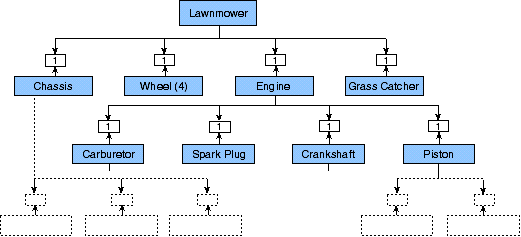
Figure 1 shows a diagram of the component structure for a power lawnmower. Note that there are many levels corresponding to assemblies and sub-assemblies, with discrete components at the bottom. Sometimes there are multiple instances of a component item (wheels, for example) connected to a parent item. Also, the same component (a screw, for example) could be used in several sub-assemblies, and there could be several finished-good items (different lawnmower models) using common sub-assemblies.

Figure 1: Lawnmower Component Structure (Partial illustration)
Different Approaches: Relational and Pointer-based Network Database Models
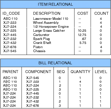
How can we model the bill of materials with a database structure? Consider first the relational approach. We need two tables, one for item records and the other for the connection records we call bill records. One item record exists for each unique part, between a parent item and component item. We need an item-ID index for the item table and a parent-ID/sequence-number index for the bill table. Given the item ID, we can find the item record and all the bill records that have the specified item as a parent. For each bill record we can get the component ID, and so on. Figure 2 shows these tables.

Figure 2. Tables for the relational model database
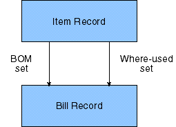
The pointer-based network model approach is illustrated by the logical schema diagram in Figure 3. The item and bill records are connected by two sets, called bill-of-materials (BOM) and where-used. Figure 4 shows an instance diagram for the lawnmower, where each rectangle represents an instance of a physical database record. Note that a parent item owns several bill records (BOM set), each of which is owned by one component item (where-used set). The components can be parents also, each owning more bills, etc. Thus you can see that the simple structure from Figure 3 can represent a very complex problem.

Figure 3: Schema Diagram for Network Database Model

Figure 4: Instance Diagram for Network Database Model (Partial Illustration)